EXPANDED METAL GRATING

The diversity of expanded metals pushes us to continually develop and improve the processes and standards used in its production. If you have need of a special material not shown within the website, please use our ‘Contact Us‘ form or give us a call. We can meet your functional or structural need.


Return to our ‘Expanded Metals‘ page, or browse our ‘Expanded Metal Grating‘, ‘Sun Shade & Micro-Mesh‘ and ‘Expanded Mini-Mesh’ pages for product specs of each type. Be sure to view the ‘Expanded Solutions Process‘ page for a technical overview of the process and terminology.

  • Grating is the most economical industrial walking surface you can install in your plant.
  • Walking surface is anti-skid, providing safe foothold.
  • The open design allows effective sprinkler coverage for fire protection; prevents dirt, grease or snow accumulation; it enables a visual ‘see-through’ area inspection; lowers maintenance costs.
  • Expanded Solutions grating costs less than bar-type or sheet metal grating and is easier to install in new or replacement applications.


Please Note:
The information provided is for descriptive purposes only – NOT FOR DESIGN

CARBON STEEL - Grating Size Chart

STYLE Lbs. Per
Sq. Ft.
Standard Sheet
Size (Feet)
Design Size
(Inches)
Opening Size
(Inches)
Strand Size
(Inches)
Overall
Thickness
(Inches)
No. of
Designs Per Ft.
 (%)
Open
Area
 
SWD LWD SWD LWD SWO LWO Width Thick-
ness
SWD LWD
 
3.0 lb. 3.00 4 & 6 8,10 & 12 1.33 5.33 .940 3.44 .264 .183 .540 9 2.25 60
3.14 lb. 3.14 4-4 & 6 8-10 2.00 6.00 1.625 4.88 .312 .250 .656 6 2 69
4.0 lb. 4.00 4-5 & 6 8 & 10 1.33 5.33 .940 3.44 .300 .215 .618 9 2.25 55
4.27 lb. 4.27 4 & 6 8 & 10 1.41 4.00 1.00 2.88 .300 .250 .625 8.5 3 58
5.0 lb. 5.00 4-5 & 6 8 & 10 1.33 5.33 .813 3.38 .331 .250 .655 9 2.25 50
                           
Aluminum
Type 5052-H-32
                         
2.0 lb. 2.00 5 12 1.33 5.33 .940 3.44 .387 .250 .730 9 2.25 48
                           
 
Please Note: This information is for descriptive purposes only - NOT FOR DESIGN

NOMINAL WEIGHTS AND DIMENSIONS*

STYLE Nominal Weight
for Lbs. Per
Sq. Ft.
Design Size
(Inches) B
Opening Size
(Inches) C
Strand Size
(Inches) C
Overall
Thickness
(Inches)
No. of
Designs Per Ft.
(%)
Open
Area
SWD LWD SWO LWO Width Thick-
ness
SWD LWD
GRATING-CARBON STEEL
2.0 lb. 2.00 1.33 5.33 1.000 3.60 .235 .135 .460 9 2.25 77
3.0 lb. 3.00 1.33 5.33 .940 3.44 .264 .183 .540 9 2.25 60
3.14 lb. 3.14 2.00 6.00 1.625 4.88 .312 .250 .656 6 2 69
4.0 lb. 4.00 1.33 5.33 .940 3.44 .300 .215 .618 9 2.25 55
4.27 lb. 4.27 1.41 4.00 1.000 2.88 .300 .250 .625 8.5 3 58
5.0 lb. 5.00 1.33 5.33 .813 3.38 .331 .250 .655 9 2.25 50
6.25 lb. 6.25 1.41 5.33 .813 3.38 .350 .312 .715 8.5 2.25 50
7.0 lb. 7.00 1.41 5.33 .813 3.38 .391 .318 .740 8.5 2.25 45
GRATING-STAINLESS STEEL
3.3 lb. 3.32 2.00 6.0 1.625 4.88 .312 .250 .656 6 2 69
4.5 lb. 4.25 1.41 4.0 1.000 2.88 .300 .250 .656 8.5 3 58
GRATING-ALUMINUM
2.0 lb. 2.0 1.33 5.33 .940 3.44 .387 .250 .730 9 2.25 48
A) 1 lb. = 0.454 kg; 1 in. = 25.4 mm.
B) A variation in weight per square ft. of ±5% is permissible, based on the weight of any sheet or bundle. No combination of tolerances can be combined to yield weight per SF below -5 % tolerance range; the minimum weight per SF of - 5 % is absolute.
C) A tolerance of ± 5 % is permitted in dimensions, center to center.

Concentrated & Uniform Load Deflection Tables/Fixed Span

  Carbon Steel - - - - - - - - - - - - - Style - Lbs. Per Sq. Ft. Aluminum
 
3 3.14 4 4.27 5 6.25 7 2
 
Load D Load D Load D Load D Load D Load D Load D Load D
 
  24"
SPAN
    U 275 .250 375 .250 350 .240 500 .245 600 .240 800 .220 800 .210    
C 275 .250 375 .250 440 .250 400 .250 540 .245 800 .220 800 .220 250 .250
 
  36"
SPAN
    U 100 .220 150 .240 150 .245 165 .245 175 .240 300 .250 400 .250    
C 165 .250 155 .250 220 .250 225 .240 310 .250 300 .240 350 .240 100 .250
 
  48"
SPAN
    U     50 .250 50 .250 60 .250 100 .250 115 .240 165 .240    
C 75 .250 75 .250 100 .250 100 .250 140 .250 150 .240 175 .250 50 .250
 
U - Uniform Load in Lbs. Per Sq. Ft. C - Concentrated Load in Lbs. Per Sq. Ft. D - Deflection in inches

Selection Chart (Carbon Steel)*

CONCENTRATED LOAD
(Lbs. Per Foot of Length
of Catwalk or Platform)
CLEAR SPAN
(Distance between supports, measured from the inside edge
of one support to the inside edge of the next support.)
 
23" 30" 35" 42" 47" 54" 60"
 
50 Lbs. Light or occasional pedestrian traffic 3.0
3.14
3.0
3.14
3.0
3.14
3.0
3.14
3.0
3.14
4.0
4.27
5.0
6.25
 
100 Lbs. Normal or frequent pedestrian traffic 3.0
3.14
3.0
3.14
3.0
3.14
4.0
4.27
5.0
6.25
7.0 7.0
 
150 Lbs. Heavy or constant pedestrian traffic 3.0
3.14
4.0
4.27
4.0
4.27
5.0
6.25
6.25 7.0  
 
200 Lbs. Pedestrian traffic with light equipment 3.0
3.14
4.0
4.27
4.27
5.0
6.25 7.0 7.0  
 
250 Lbs. 4.0
4.27
5.0 5.0
6.25
7.0 The concentrated load
deflections for this chart do
not exceed the 1/4" maximum
deflection as stated by Federal
Specification RR-G-661B
and the generally accepted
recommendation for normal
pedestrian comfort.
 
300 Lbs. 4.0
4.27
5.0
6.25
6.25  
 
350 Lbs. 4.0
4.27
6.25 7.0  

* Sizes listed do not imply availability

Installation Procedures

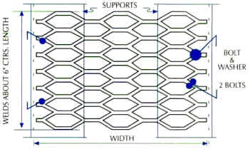
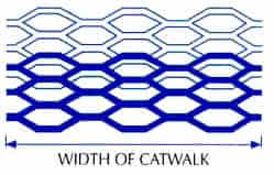
For maximum load, position Long Way of Design parallel to the clear span. LWD must be installed parallel to span. Butt or overlap one half of design. No increase in overall thickness.


Bolt or weld every 6 inches or every fourth design to rigid supports.

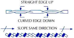
Install with straight edge up (top – straight edge, bottom – rounded edge). Bonds of adjoining should slope in same direction and align with adjoining pieces.

This information is provided for illustration purposes only – NOT FOR DESIGN. Confirm all load information with your engineer or architect.

Machine Guards - OSHA Expanded Metal Size Chart *

Clearance From Moving Parts At All Points. Largest Mesh Approved Minimum Gauge or Thickness Recommended Expanded Metal Style Number
under 4" 1/2" #18 1/2"-#18 STD
1/2"-#16 FLAT or STD
1/2"-#13 FLAT or STD
4" - 15" 2" #13 1/2"-#13 FLAT or STD
3/4"-#9 FLAT or STD
1 1/2"-#9 FLAT or STD
*Extract from Table 0-12 OSHA
Table of Standard Material and Dimensions.
Subpart 0, Machine Guarding,
Paragraph 1910.2199, Page 10650.